PICA: Advanced High-Precision Transport Measurement Automation with Python
Comprehensive Guide for Version 1.0.5
Note
v1.0.5 is now live! Lakeshore enhancements, new utilities & core fixes. Install or upgrade via pip:
pip install --upgrade pica-suite
v1.0.6 is coming soon — bringing Novocontrol Alpha-A broadband dielectric spectroscopy (experimental), an interactive SCPI console, and plotting engine improvements.
Table of Contents
1. Overview
High-precision, low-noise transport measurements are essential for advancing research in spintronics and materials characterization. To enable such progress, highly precise and accurate automation software is required. PICA (Python-based Instrument Control and Automation) is a modular, open-source software suite designed to automate advanced transport measurements for electronic devices and material samples. PICA is designed as a versatile framework capable of operating on any standard laboratory workstation.
It provides an extensible, unified graphical user interface (GUI) for orchestrating high-precision instruments, specifically current source (DC/AC) units, nanovoltmeters, high resistance electrometers, impedance analyser, and temperature controllers. Built on the robust Python scientific ecosystem, PICA leverages community standard libraries as an alternative to licensed commercial software for instrument control.
By utilising threading and multiprocessing capabilities, PICA ensures that the entire hardware ecosystem functions seamlessly and as a single cohesive unit. This allows the system to perform automated protocols, including temperature-dependent wide range resistance measurement (10-8 - 1016 Ω), current voltage (I-V) characterisation, capacitance characterisation, and pyroelectric current measurement, and orchestrates measurements under varying magnetic fields and temperatures without requiring physical reconfiguration of the measurement setups.
2. Design Philosophy & Architecture
PICA was constructed on a core philosophy of robustness, modularity, and accessibility, prioritizing open standards over proprietary “black box” solutions.
2.1 The Choice of Python
Python was selected as the foundational language for PICA due to its ubiquity in the scientific community:
Scientific Ecosystem: Libraries like
NumPy(array operations),Pandas(data structuring), andMatplotlib(publication-quality plotting) create a seamless workflow from acquisition to analysis.PyVISA Integration: The
PyVISAlibrary provides platform-independent wrappers for VISA drivers, allowing communication via simple, readable commands (e.g.,instrument.query('*IDN?')) rather than complex low-level protocols.Cross-Platform: PICA runs on Windows, Linux, and macOS with minimal modification, accommodating diverse lab environments.
2.2 The Case for GUIs
While early automation scripts often rely on Command Line Interfaces (CLIs), the final PICA suite prioritizes full-featured GUIs built with Tkinter. This strategic decision was guided by:
Error Prevention: GUIs employ input validation and dropdown menus to restrict parameters to safe/logical ranges, preventing the “invalid command” errors common in CLI environments.
Real-Time Feedback: Embedded
Matplotlibplots provide immediate visualization of incoming data. This allows researchers to spot physical anomalies, noise, or connection issues instantly, potentially saving hours of wasted experimental time.Workflow Visualization: A visual interface helps new users and students mentally map the experimental workflow, reducing the learning curve.
2.3 Operational Transparency (No “Black Box”)
To foster trust and reproducibility, PICA rejects the opaque nature of proprietary software. measurement module features an Embedded Console Log:
Status Streaming: Displays a real-time stream of operations, such as “Ramping temperature to 300 K” or “Connecting to GPIB0::4::INSTR”.
Immediate Diagnostics: Instantly reports VISA timeouts or command errors, providing exact context for hardware failures rather than generic error codes.
2.4 Architecture: Process Isolation
PICA employs a multiprocess architecture using Python’s multiprocessing library.
Frontend (GUI): Handles user interaction and live plotting.
Backend (Logic): Executes in a separate, isolated process. This ensures that if a measurement script hangs due to a hardware timeout, it does not crash the main application, preserving the stability of the suite and other concurrent tasks.
2.5 Self-Contained and Modular Programs
In PICA, each program is designed to be self-contained. This architectural choice reduces dependency chains and mitigates the excessive abstraction layers that can make other projects difficult to understand or modify. Each program (i.e., each Python file or module) can operate independently, thereby facilitating debugging and maintenance.
This approach, however, leads to a considerable degree of code repetition because there are relatively few abstractions. Nevertheless, this trade-off can be advantageous in experimental environments, where the primary objectives are comprehensibility, maintainability, usability, and stability over extended periods, rather than strict adherence to principles of code elegance or minimal redundancy. In such contexts, scripts may remain functional without requiring updates for many years.
3. Installation & Setup
3.1 System Prerequisites
System Requirements & Compatibility
Supported Platform: Windows 10 / 11 Architecture: x86_64
Important
Windows Only PICA is currently designed and validated exclusively for Windows environments. Linux and macOS are not currently supported due to dependencies on Windows-specific GUI libraries and font rendering. Attempting to run this software on non-Windows platforms may result in crashes or UI failures. Linux support is experimental for now.
Software Dependencies
Python 3.10+: The core execution environment.
Dependencies: Install via
pip install -r requirements.txt.
Warning
A VISA Backend is Required: PyVISA is a Python wrapper, not a driver. For PICA to communicate with hardware, you must install a VISA backend on your system first. If you attempt to run the software on a clean machine without a VISA implementation, it will fail to find the instruments. This is the most common failure point for new instrument control setups.
Choose one of the following:
NI-VISA: The industry standard from National Instruments. Download and install it from the NI website.
PyVISA-py: A backend written in pure Python. It can be used as a fallback but may have limitations compared to vendor-specific drivers like NI-VISA. For
pyvisa-pyto discover all resources and avoid warnings (e.g., for TCPIP or HiSLIP instruments),psutilandzeroconfmight be needed. These packages are already included in PICA’s dependencies (requirements.txt). Note that for direct GPIB communication viapyvisa-py, a separate GPIB library (e.g., from your GPIB adapter vendor) might still be required. PyVISA-py GitHub
Before proceeding, verify your VISA installation. For more details and troubleshooting, refer to the “Common Issues & Troubleshooting” section.
3.2 Getting Started
PICA is structured as a standard Python package. The following instructions are for the supported Windows platform.
Clone the Repository
git clone https://github.com/prathameshnium/PICA-Python-Instrument-Control-and-Automation.git
cd PICA-Python-Instrument-Control-and-Automation
Create Virtual Environment & Install
# Create and activate a virtual environment
python -m venv venv
venv\Scripts\activate

# Install the package and its dependencies
pip install .
To update PICA to the latest version, run the following command in the project directory:
pip install --upgrade .
If you are already in your virtual environment and want to force Python to reinstall the package (overwriting the old one), run this in your root project folder:
pip install --force-reinstall .
Note: Ensure you have the NI-VISA drivers installed on your host machine to allow
PyVISAto communicate with the hardware.
3.3 Running the Software
Graphical Launcher (Recommended) The central dashboard for accessing all modules, the plotter, and the scanner.
pica-gui
The PICA Launcher provides a centralized dashboard for all measurement suites. While each module can be launched directly from its card, the launcher also provides a quick way to access the underlying scripts for editing. For developer convenience, each measurement suite card includes a folder icon (📁) in the top-right corner. Clicking this provides a shortcut to the module’s Python scripts, allowing for rapid modifications.
You can also run any of the individual GUI measurement modules independently. This is useful for quickly accessing a specific measurement without opening the main launcher. To do this, simply run the Python script for the desired module. For example:
python pica/keithley/k6517b/High_Resistance/IV_K6517B_GUI.pyLauncher v2 (in testing) A second launcher ships alongside the classic one. It opens on the Quick Select screen — three dropdowns (category, module, protocol) that narrow a measurement down in plain language — and keeps the full card grid in an Advanced Options window (
Ctrl+Shift+A). See Launcher v2.python run_pica_v2.pyCommand Line Interface (CLI) For headless operation (e.g., Raspberry Pi).
pica-cli
Important
Template Scripts: The instrument control modules (CLI’s) provided are designed as template scripts. Users are expected to modify these scripts programmatically to adapt them to their specific experimental requirements and custom workflows. They are also excellent for developing custom measurement protocols, sequences, and for learning instrument automation. These scripts are typically named with an ‘Instrument_Control’ suffix to denote their programmatic nature. This approach ensures maximum flexibility and customization for advanced research applications.
Note
Legacy CLI Notice: The PICA CLI (pica-cli) is retained to support legacy headless workflows. While fully functional for specific protocols, this interface is less frequently maintained and may not support recent features available in the GUI.
We strongly recommend new users utilize the PICA GUI for the most complete and supported experience.
3.4 Development Dependencies for Testing (Optional)
If you plan to contribute to PICA or run the test suite, you will need to install the development dependencies:
pip install -r requirements-dev.txt
How to Check Coverage Locally
To see the coverage percentage on your local machine, run this command instead:
python -B -m pytest --cov=pica --cov-report=term-missing -p no:cacheprovider
Experimental Linux Instructions
Warning
Experimental Support: The following instructions are for experimental purposes only. PICA is not officially supported on Linux (for now), and you will likely encounter functional or UI-related issues.
For users who wish to experiment with PICA on Linux, please be aware of the following:
Prerequisites:
Tkinter Dependency: On Linux, you must ensure
tkinteris installed, as it is often not included by default.On Debian/Ubuntu:
sudo apt-get install python3-tkFor other distributions, use your package manager to install
python3-tk.
Virtual Environment Activation: To activate the virtual environment, use:
source venv/bin/activate
Installation: Follow the standard installation steps outlined in section 3.2 Getting Started. While the commands should run, be aware that the application GUI may not function correctly.
4. Safety Precautions
Warning
Safety Instructions: Always switch off the instrument and verify that the output current, voltage, and any other relevant parameters are set to zero before modifying the connections to the Device Under Test (DUT). Failure to follow appropriate safety procedures may result in electric shock or other hazards. Adopt a safety-first approach at all times, and ensure that all instrument parameters remain within the specified safe operating limits defined either by the instrument manufacturer or by your measurement setup.
5. Core Utilities
5.1 VISA Instrument Scanner
File Reference: pica/utils/GPIB_Instrument_Scanner_GUI.py
Automatically launched upon startup (and accessible within modules), this utility scans for connected hardware. It uses ResourceManager.list_resources() to find devices and sends a standard *IDN? query to verify communication. This allows users to verify their hardware configuration before starting any experiment. The VISA scanner also includes an address guide, which can be edited by the user for quick reference.
In the main PICA launcher, the VISA/GPIB scanner is configured to execute automatically at application startup. This design choice is motivated by the fact that initiating a measurement without first verifying the instrument connection is highly likely to fail and may result in non-informative error messages, such as a VISA connection timeout.
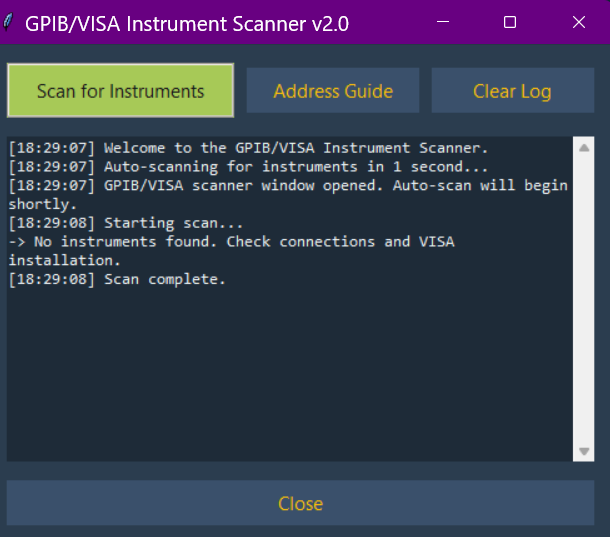
The PICA Instrument Scanner utility, which automatically detects and identifies connected instruments.
5.2 PICA Plotter Utility
File Reference: pica/utils/PlotterUtil_GUI.py
A standalone, multiprocessing-enabled tool for detailed data analysis. Unlike the minimalist embedded plots in the measurement modules, this utility allows:
Comparative Analysis: Overlaying multiple
.csvor.datfiles.Live Updates: Monitoring active experiments by auto-refreshing data from disk.
Flexible Axis Control: Toggling linear/log scales to analyze data spanning orders of magnitude.
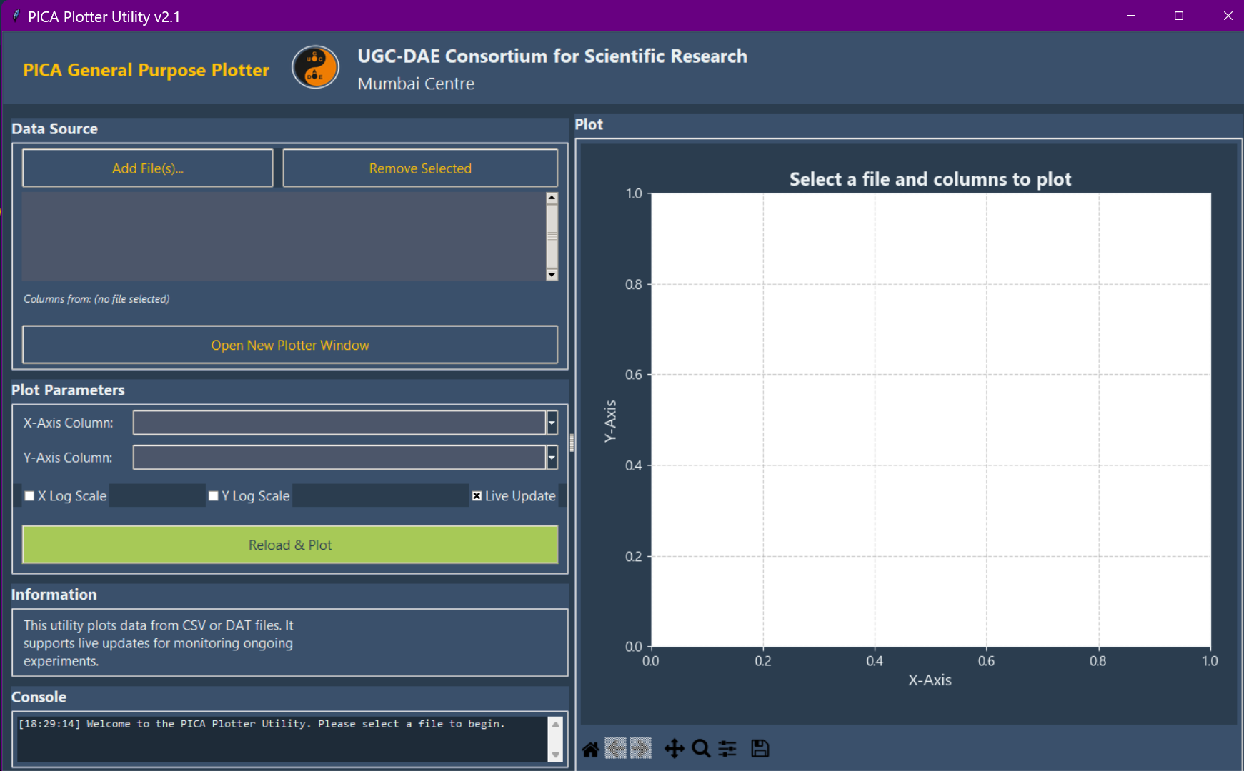
The PICA Plotter Utility, a tool for data visualization and comparative analysis of multiple datasets including live plotting.
5.3 Embedded Document Viewer
To ensure the software is self-contained (useful for offline lab computers), PICA includes an in-app viewer for project documentation, including this User Manual, the Instrument Manuals List, the License, and the Changelog.
5.4 Measurement Module Interface
Each measurement module consists of two primary windows: the control window on the left and the plotter window on the right. The dimensions of both windows are resizable. Upon launching a measurement module, it is recommended to first enlarge the control window, as it is required for configuring all experimental parameters. Typical settings include specifying the sample file name, selecting the file storage location, choosing the instrument address via a selection box, and defining voltage and temperature step sizes, delays, and other experimental parameters.
The control window also contains a console located below the parameter settings. This console can be scrolled and provides a continuous log of all operations executed by the software. The right-hand plot window is a simplified plotting interface that can display one, two, or three plots, depending on the specific module. The plots are updated in real time, and some modules allow switching the axes to a logarithmic scale to improve data visualization. The plotting interface is intentionally kept minimalistic, with limited functionality, to reduce unnecessary user interaction with the measurement setup, and maintaining the measurement program in a simplified form by omitting nonessential features.
Above the plot area, there are two buttons providing access to the VISA Instrument Scanner and PICA Plotter Utility. These utilities are accessible from all modules to facilitate rapid testing and diagnostics. The VISA/GPIB scanner allows the user to quickly verify whether instruments are properly connected and recognized by the system, while the plotter utility offers additional plotting capabilities beyond those available in the default plot window.
5.5 Launcher v2: Quick Select and Advanced Options
File Reference: pica/main_v2.py (run with python run_pica_v2.py)
Launcher v2 is a second dashboard, developed alongside the classic launcher
(pica-gui), which it does not replace. It exists because the two people who
use PICA want opposite things from it: someone meeting the instrument rack for
the first time wants to be asked what they are measuring, and someone who runs
the rack every day wants every module on one screen. v2 gives each of them a
window.
Quick Select (the main screen). Three dropdowns, answered in the order a person actually thinks in:
Category — DC Resistance, AC Resistance, Impedance Spectroscopy or Pyroelectric.
Module — the resistance range or the measurement style. Under DC Resistance: Ultra Low Resistance (10 nΩ – 1 µΩ), Low Resistance (above 1 µΩ), Resistance, High Precision (1 µΩ – 100 MΩ), Normal Resistance (100 µΩ – 200 MΩ) and High Resistance (1 Ω – 10 PΩ). Ultra Low and Low run the same delta-mode scripts; they are listed separately because a 10 nΩ contact and a 10 mΩ film are different measurements to the person making them, whatever the instrument pair.
Protocol — the individual measurement, e.g. an I–V sweep, an R vs. T where PICA drives the temperature, or an R vs. T where PICA only reads it.
Each choice also narrows the instrument list shown on the status strip, with each instrument’s own light: picking a category shows everything its modules can use, picking a module shows that module’s hardware, and picking a protocol shows only what that script talks to — an I–V sweep drops the temperature controller entirely, and a T Sensing (Cryocon 34) protocol drops the Lakeshore. “Do I have the hardware for this, and is it switched on?” is therefore answered where the choice is being made.
Each choice writes a short description of itself into the panel below, so all three levels — what the measurement is, what range it covers, what the protocol does — are on screen at once before anything is launched. The descriptions name every instrument in full (“Keithley 2400”, not “K2400”), since this screen is the one place in PICA that assumes no prior familiarity with the rack.
The Cryo-con 34 appears in Quick Select under the LCR meter and the electrometer only — the two benches it serves — where its protocols sit next to the Lakeshore 350 ones. Every other module is Lakeshore 350 here; the Cryo-con twins of those scripts still exist and are in Advanced Options.
Advanced Options (Ctrl+Shift+A, or the Tools menu). The complete card
grid: every module PICA ships, grouped by measurement range and instrument,
with the folder shortcut on each card. Nothing here is filtered or
range-limited — this is the expert route, and the one to use for the
temperature utilities, the Novocontrol Alpha-AN and the bench multimeter,
which Quick Select does not list. The window opens maximised and reflows its
cards into up to four columns, so a wide screen shows more of them before you
scroll; its bottom strip is the compact one, with the Instrument Status button
in place of the chips.
Console. Everything the launcher does is logged, whether or not anything is showing it. Quick Select keeps it behind the Console button on the strip, which opens it in a window of its own; Advanced Options carries one inline, above its strip. A console opened after the fact still shows the lines written at startup, and every open view updates together.
Status strip. Both windows carry a band along their bottom edge. On Quick Select it holds only what a measurement actually needs to know before it starts — the temperature snapshot, a pressure tile (a placeholder: no gauge is on the bus yet, and the tile is drawn now so the strip does not change shape when one arrives), and a button reading, for example, Instrument Status 3/10 on the bus. Advanced Options keeps the whole instrument list on its strip, chip by chip.
Instrument Status window. It opens by itself a moment after the launcher starts, and fills in when the first scan lands (so it still appears, and still explains itself, when PyVISA is missing or the VISA backend errors). After that it is opened from the strip button — launching a measurement does not raise it, which would only bury the module you just asked for. Launching does repaint the bottom panel of every open window; it does not rescan, because a module that has just started is opening its own connections and the launcher must stay off the bus. Press Reload for a deliberate rescan. The window is the launcher’s own VISA scanner:
every known instrument as a chip with its light. The dot key reads green ● — on the bus and answering (the dot blinks), grey ● — not found on the last scan, hollow ○ — never probed (the Novocontrol Alpha-AN is permanently in this state; see the GPIB runbook for why).
an instrument that answers but matches nothing in the reference table gets a chip of its own, named from its
*IDN?reply and marked (new) — so a newly racked instrument shows up without anyone editing PICA first.the instruments the current Quick Select choice needs are marked with an accent bar.
below the chips, the VISA / GPIB scan table: every resource, what it was identified as, and the raw reply. It is filled from the pass that lit the dots — no address is opened twice to build it — and appears half a second after the lights settle.
Full VISA / GPIB Scanner opens the standalone scanner utility (§5.1), unchanged, for the address guide and for sending SCPI by hand. It is not opened at startup — it repeats, in a second process and a second pass over the bus, what this window already shows — but it does come up with Advanced Options by default, and it is in the Tools menu and on the toolbar.
Important
The strip is filled by a single read-only scan at startup, and again only when Reload is pressed. The launcher never polls in the background, so once a measurement is running it stays off the GPIB bus. Pressing Reload while a measurement launched from that window is still alive raises a confirmation first.
6. Supported Measurement Modules
The system is currently validated with industry-standard hardware, covering a resistance range spanning 24 orders of magnitude, 10-15 resolution pyroelectric current measurements, and capacitance characterisation from 20 Hz - 2 MHz.
Module |
Configuration / Instrument |
Use Case |
Range |
|---|---|---|---|
Ultra Low Resistance Measurements |
Keithley 6221 + K2182 + Lakeshore 350/340 |
Superconductors & metallic films; cancels thermal EMFs via AC Delta method. |
10 nΩ - 100 MΩ |
Mid-Resistance (Standard) |
Keithley 2400 SourceMeter + Lakeshore 350/340 |
Semiconductors, oxides, general transport. |
100 µΩ - 200 MΩ |
Mid-Resistance (High-Precision) |
Keithley 2400 + K2182 + Lakeshore 350/340 |
Detecting subtle phase transitions. |
1 µΩ - 100 MΩ |
High-Resistance |
Keithley 6517B Electrometer + Lakeshore 350/340 |
High bandgap materials, polymers, & ceramics. |
1 Ω - 10 PΩ |
Capacitance Analysis |
Keysight E4980A + Lakeshore 350/340 |
C-V Analysis and Magnetocapacitance characterization. |
20 Hz - 2 MHz |
Broadband Dielectric |
Novocontrol Alpha-AN + ZG4 |
Permittivity, electric modulus & AC conductivity (WinDETA-compatible). |
3 µHz - 20 MHz |
Pyroelectric |
K6517B + Lakeshore 350/340 |
Current vs Temp (detecting Curie temperature). |
10-15 A Resolution |
While the current implementation drives specific instruments, the underlying framework is highly customizable. Researchers need only replace specific SCPI commands to utilize the suite with different models.
PICA is designed to be as versatile, while being optimized for specific classes of instruments. The following modules represent the core capabilities of the suite, supporting a resistance scale spanning 24 orders of magnitude (10 nΩ to 10 PΩ) depending on the hardware used. Pyroelectric measurement performed using an electrometer enables highly sensitive characterization of ferroelectric phase transitions by detecting extremely small pyroelectric currents, with a resolution on the order of 10-15 A. The impedance analyzer enables the characterization of capacitance anomalies over the frequency range from 20 Hz to 2 MHz and is utilized for magnetocapacitance and photoinduced characterization across a wide variety of multiferroic systems.
6.1 Ultra Low Resistance Measurements
Target Hardware: Keithley 6221 (Current Source) + K2182 (Nanovoltmeter). Typical Range: 10 nΩ to 100 MΩ.
Scientific Objective: Ideal for superconductors, metallic films, and low-impedance devices. It actively cancels thermal offsets (Seebeck EMFs) generated in leads and contacts.
Principle: Uses the AC Delta Method.
Note
Understanding “Delta Mode”: The term “Delta Mode” refers specifically to a technique used by Keithley Models 6220 and 6221 Current Sources in conjunction with the Model 2182/2182A Nanovoltmeter for very low resistance measurements. This method is described in detail in the Keithley Low Level Measurements Handbook. In this documentation, “Ultra Low Resistance Measurements” is used as the general scientific term, while “Delta Mode” may appear when specifically referencing the Keithley-specific method or program files.
Source +I, measure V1.
Source -I, measure V2.
Compute V_corr = (V1 - V2) / 2.
The software synchronizes the source and voltmeter via a hardware trigger link (RS-232) for microsecond-level timing.
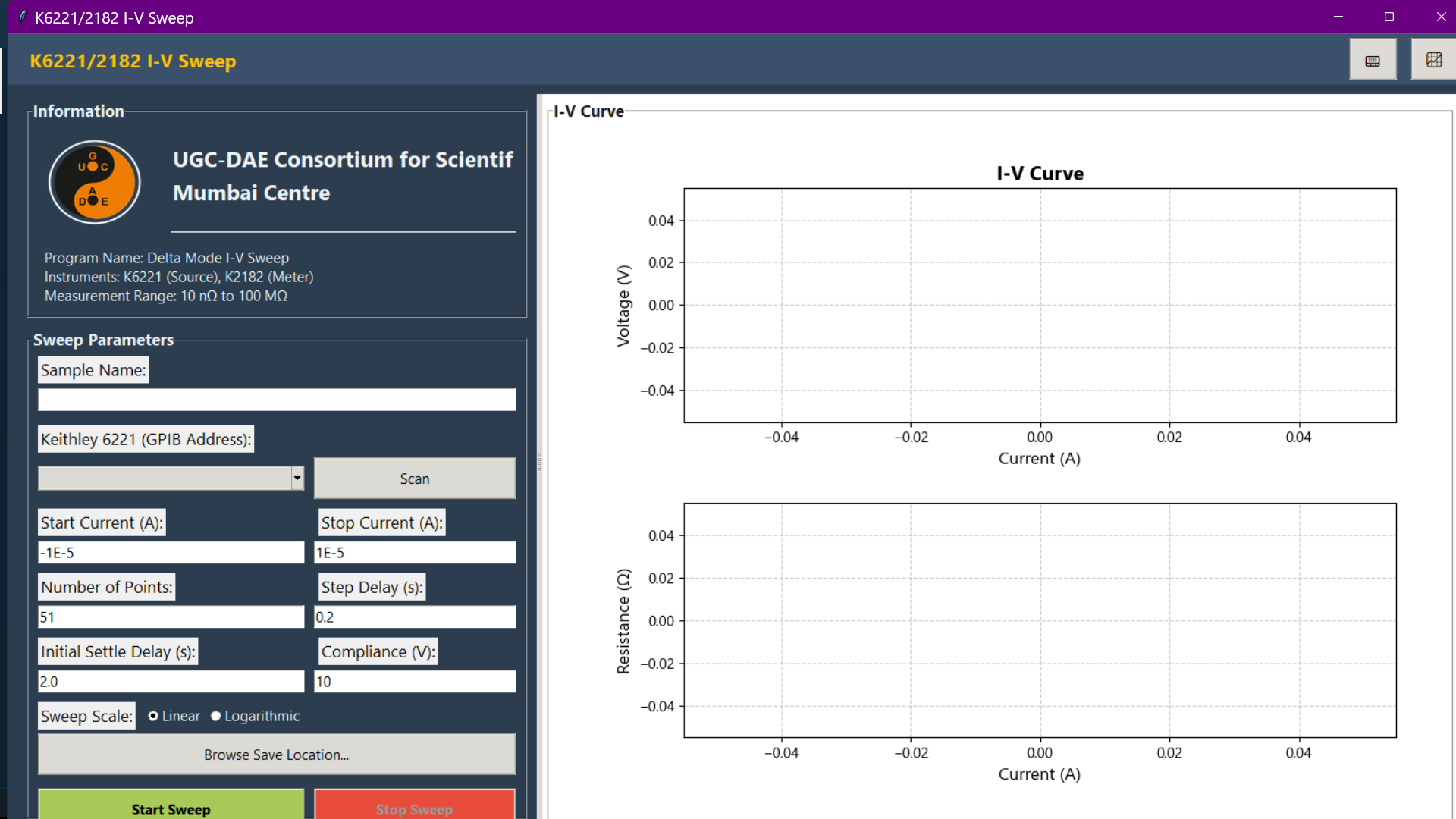
I-V sweep measurement using the Sweep Mode, designed for low-resistance measurements with a Keithley 6221 and 2182.
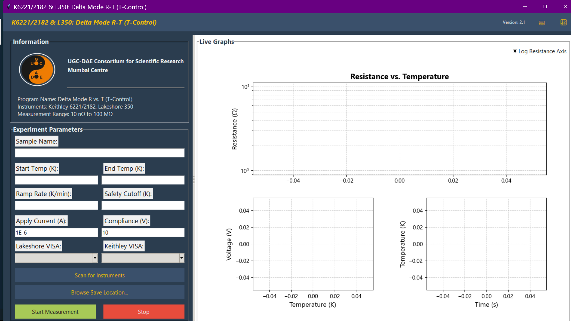
Ultra Low Resistance Measurement R-T measurement with active temperature control, using a Keithley 6221, K2182, and a temperature controller.
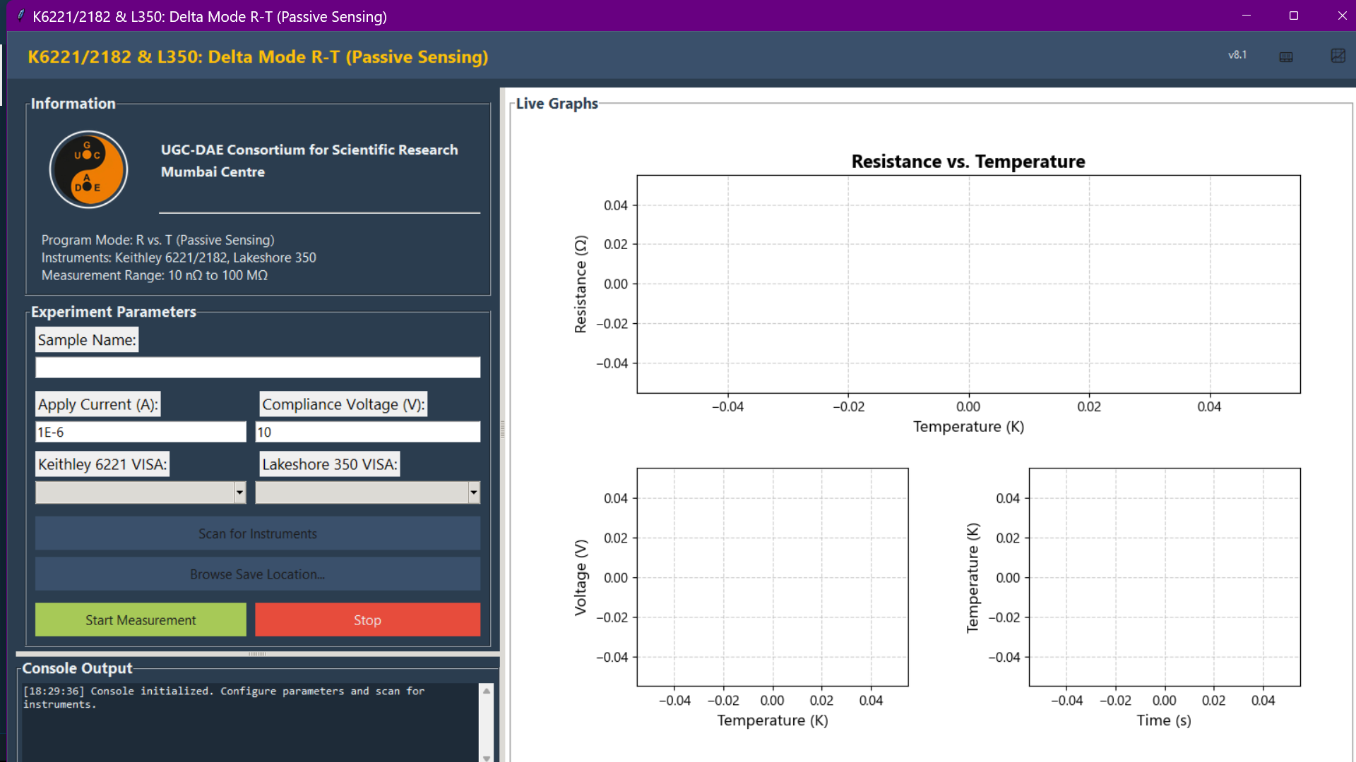
Ultra Low Resistance Measurement R-T measurement in sensing mode, where the system logs resistance and temperature while an external system manages temperature.
6.2 General Transport (Standard I-V & R-T)
Target Hardware: Keithley 2400 SourceMeter (SMU). Typical Range: 100 µΩ to 200 MΩ.
Scientific Objective: General transport characterization for semiconductors, oxides, and devices.
Capabilities:
I-V Sweep: Linear sweeps, hysteresis loops, or custom current lists.
R-T Active Control: Applies constant DC current while coordinating with a temperature controller (e.g., Lake Shore 350) to ramp temperature.
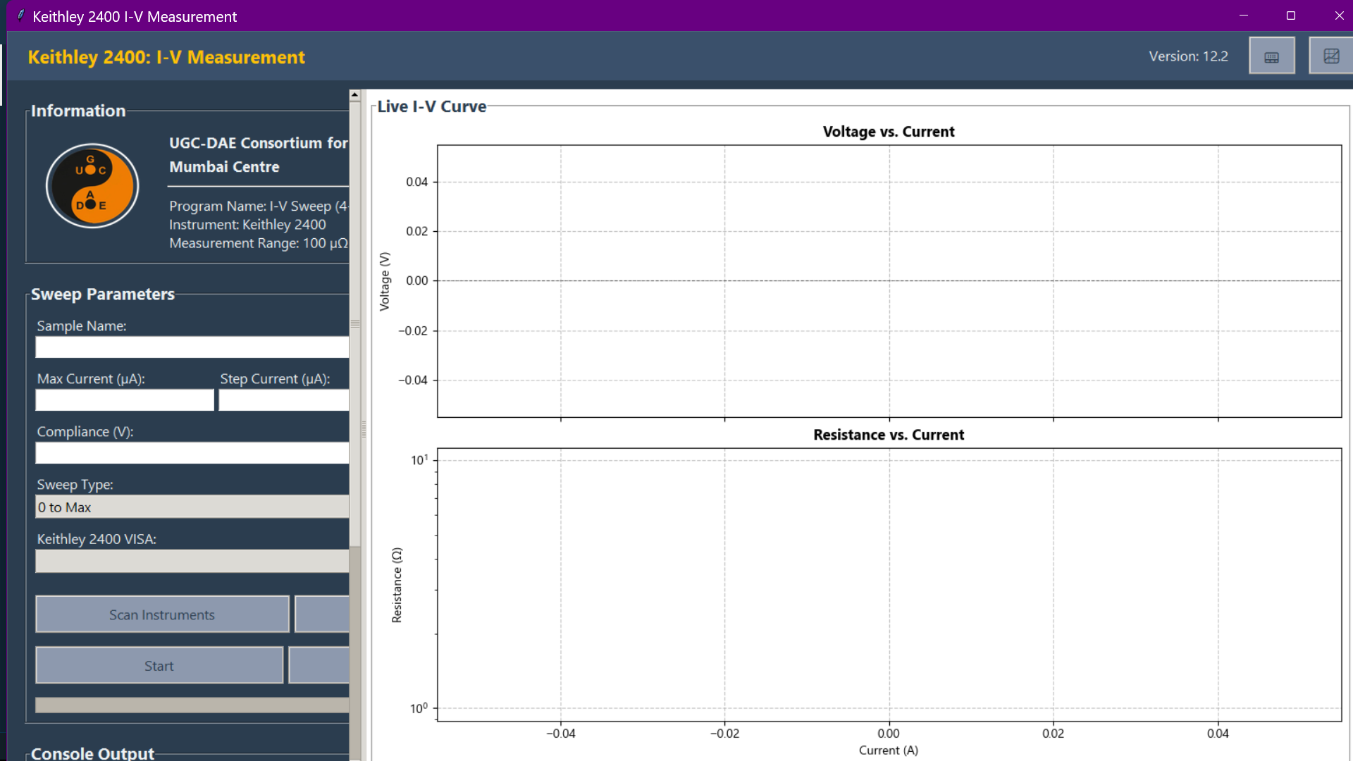
A standard I-V sweep performed with a Keithley 2400 SourceMeter, suitable for general-purpose device and sample characterization.
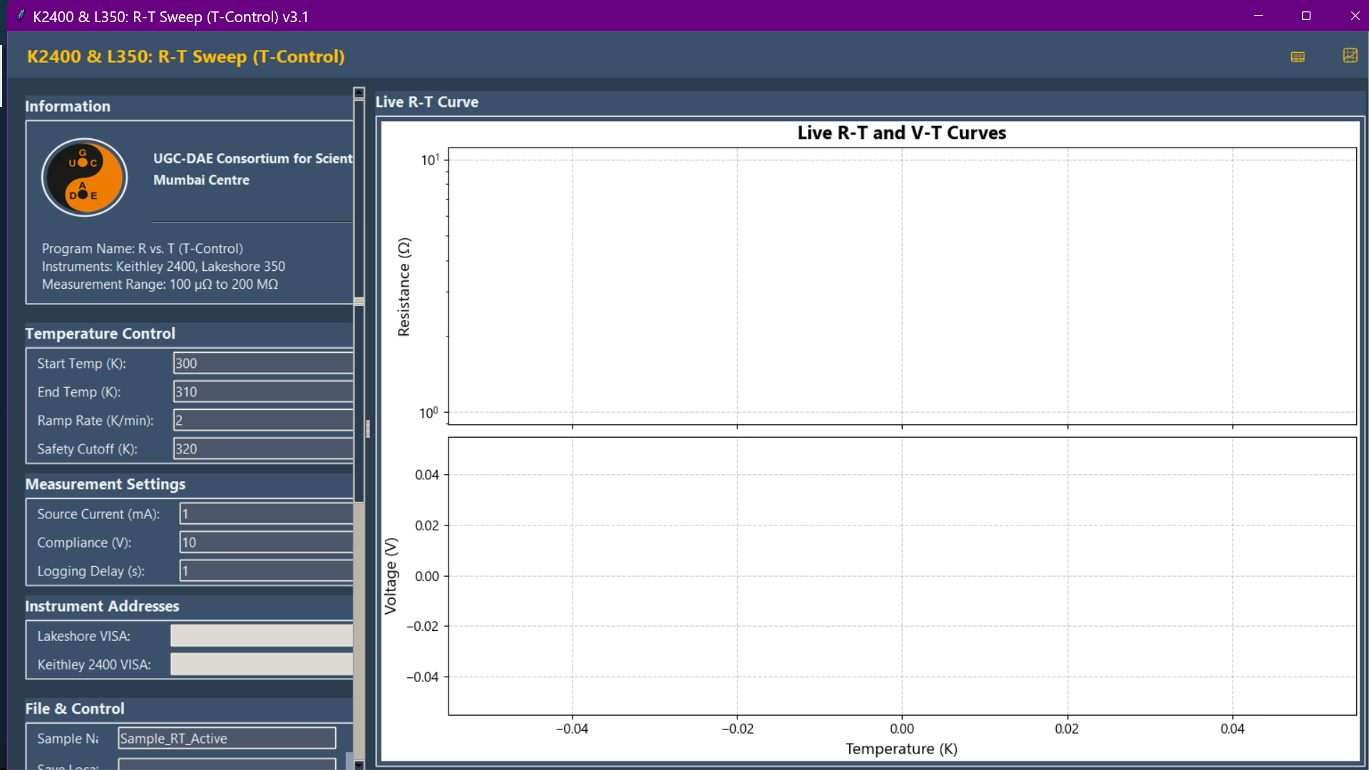
Resistance-Temperature (R-T) measurement with active temperature control, using a Keithley 2400 and a Lakeshore 350 controller.
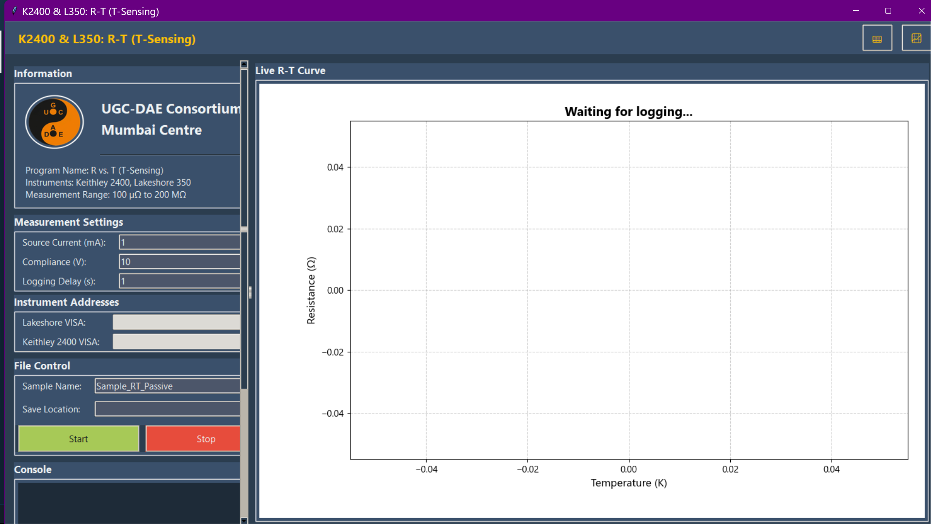
Resistance-Temperature (R-T) measurement in sensing mode, where the system logs resistance and temperature while an external system/controller manages temperature.
6.3 High Precision Transport (mid resistance range)
Target Hardware: Keithley 2400 (Source) + K2182 (Nanovoltmeter). Typical Range: 1 µΩ to 100 MΩ.
Scientific Objective: Detects subtle phase transitions in semiconductors and oxides where standard SMU resolution is insufficient.
Advantage: Combines the stable sourcing of the SMU with the nanovolt-level sensitivity of a dedicated voltmeter, utilizing a true 4-wire configuration to eliminate lead resistance errors.
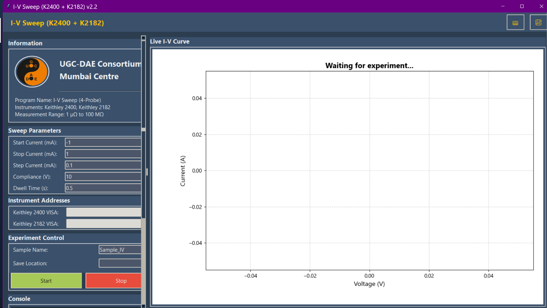
High-precision I-V characterization using a Keithley 2400 as a current source and a Keithley 2182 nanovoltmeter for sensitive mid-range resistance measurements.
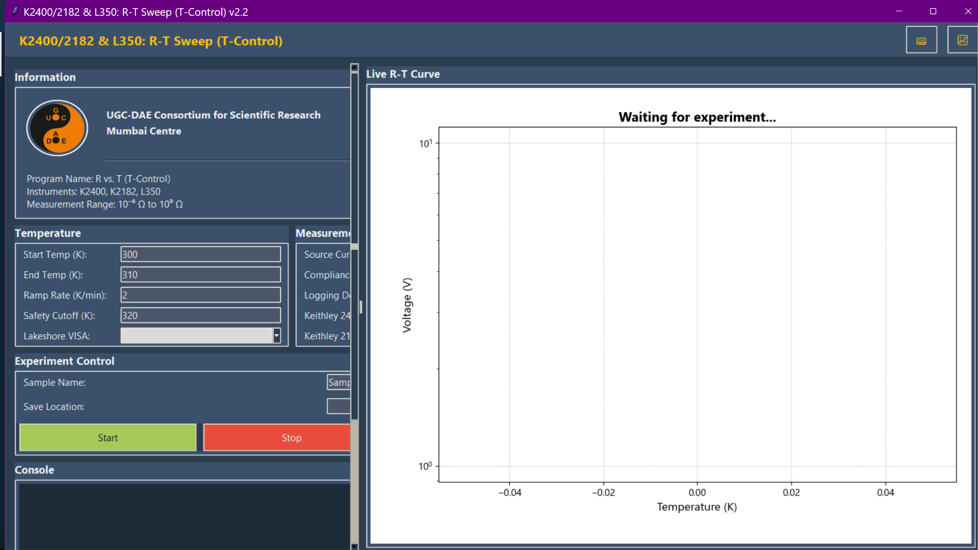
High-precision R-T measurement with active temperature control, combining the K2400, K2182, and a L350 temperature controller.
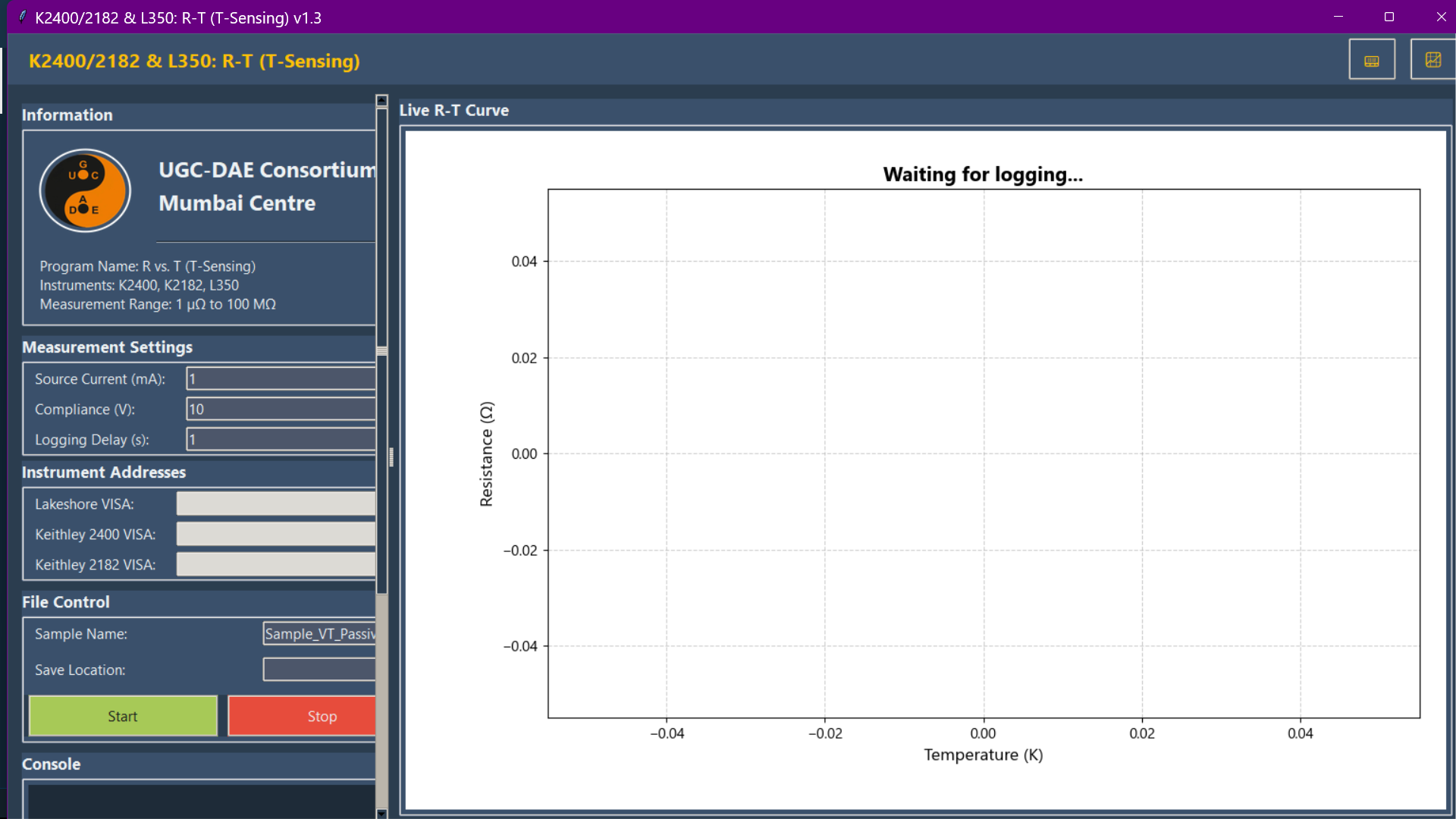
High-precision R-T measurement in sensing mode, leveraging the K2400 and K2182 for enhanced accuracy for mid-range resistance measurements.
6.4 Electrometry & High Resistance
Target Hardware: Keithley 6517B Electrometer (or compatible High-R meter). Typical Range: 1 Ω to 10 PΩ (1016 Ω).
Scientific Objective: Characterization of capacitances, polymers, and ceramics (Electrometry).
Principle (Voltage Driven): Applies a high voltage and measures the resulting leakage current (pA/fA range).
Note: PICA manages instrument settling times, allowing for a necessary initial delay for the system to stabilize. This is crucial in high-impedance setups to ensure steady-state ohmic currents are accurately recorded.
A screencast demonstrating the high resistance IV module is available at this link.
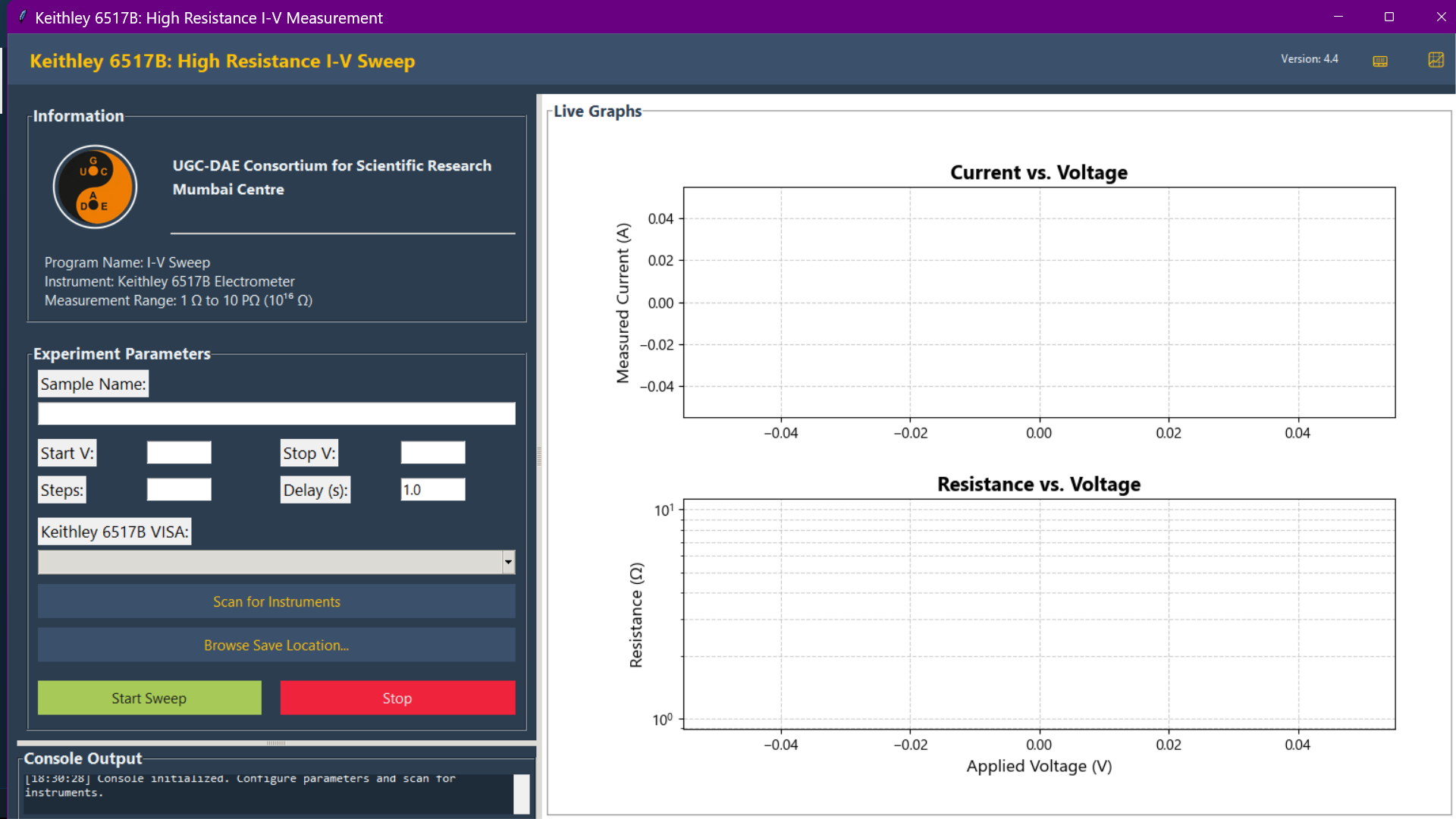
High-resistance I-V measurement performed with a Keithley 6517B Electrometer, designed for characterizing insulating materials.
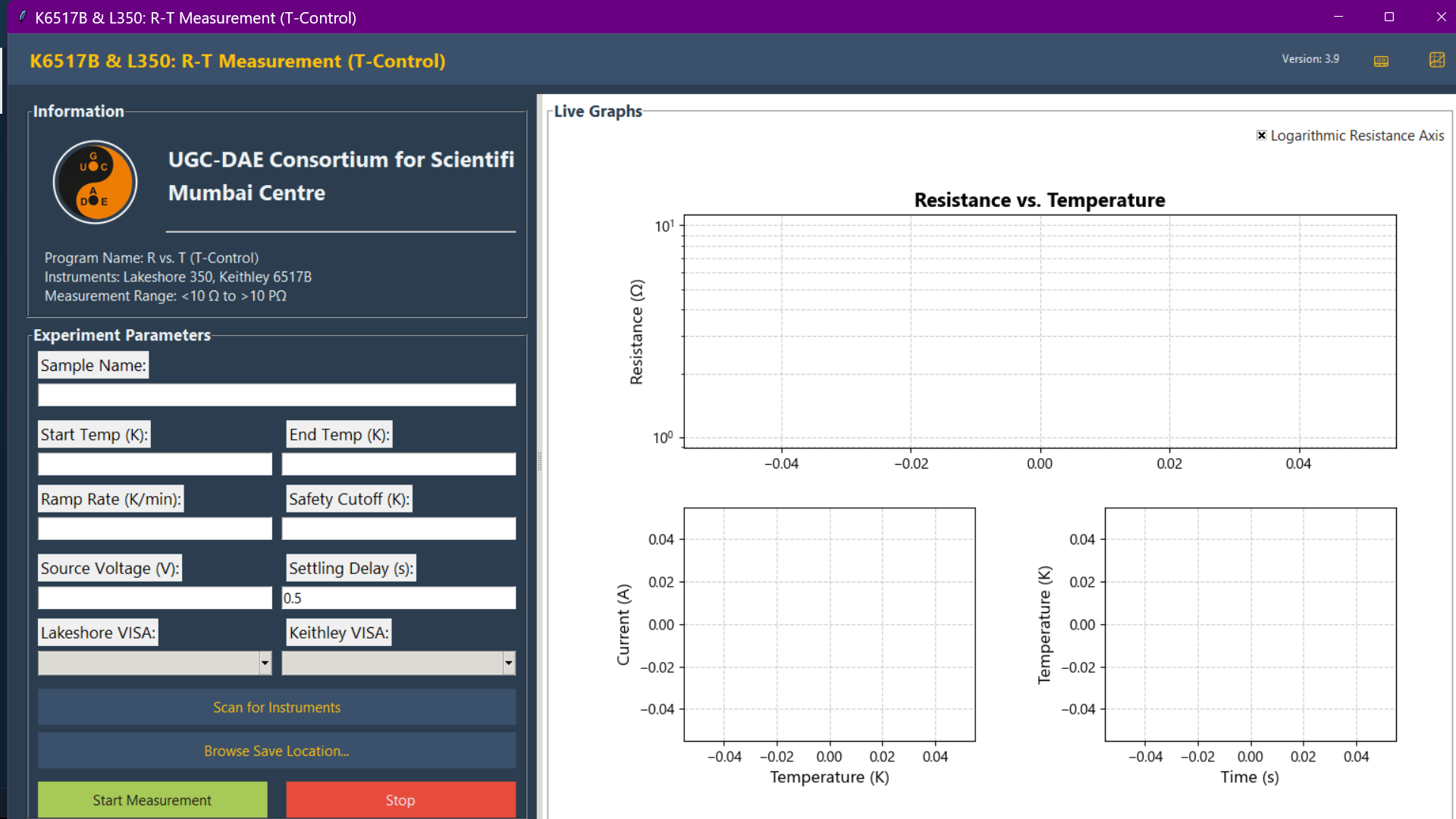
High-resistance R-T measurement with active temperature control using a Keithley 6517B.
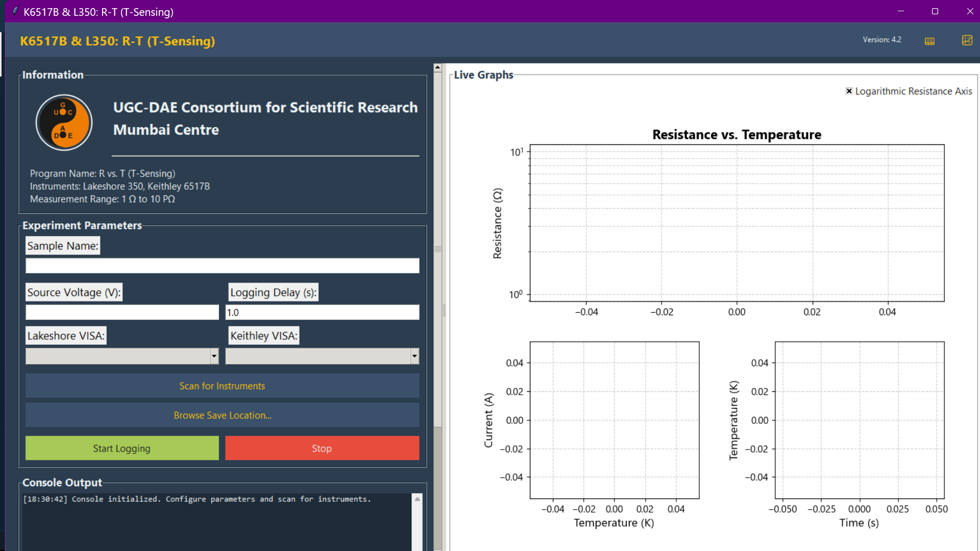
High-resistance R-T measurement in passive sensing mode using a Keithley 6517B.
6.5 Pyroelectric Current Measurements
Target Hardware: Keithley 6517B Electrometer + Temperature Controller. Sensitivity: Down to 1 fA (10-15 A).
This module automates the measurement of pyroelectric currents (Ip) as a function of temperature, commonly used to characterize ferroelectric phase transitions and identify Curie Temperatures (Tc).
Workflow:
Poling (Optional): Apply bias field while cooling.
Heating: Remove bias; heat sample at a linear rate.
Measurement: Record the depolarization current peak indicative of phase transition.
Best Practice: For measurements in the fA range, ensure your setup utilises proper shielding (e.g., double-layer Faraday cage).
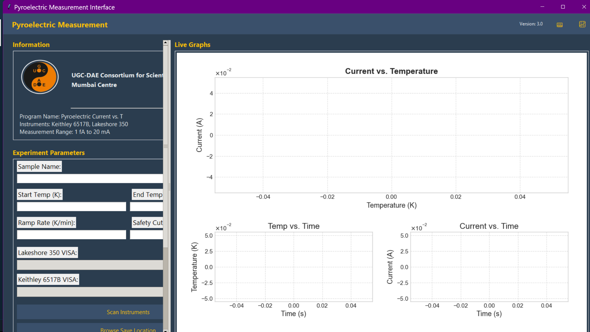
Pyroelectric current measurement as a function of temperature, captured with a Keithley 6517B to identify ferroelectric phase transitions via measuring pyroelectric current.
6.6 High Voltage Poling
Target Hardware: Keithley 6517B (Voltage Source). Capabilities: High Voltage Sourcing.
This utility provides a dedicated interface for In-situ and ex-situ electrical poling of materials.
Objective: Establish a uniform ferroelectric polarization state in samples before characterization.
Applications: Preparing samples for pyroelectric current measurements, converse magnetoelectric studies, and ex-situ neutron diffraction studies on poled materials.
6.7 Dielectric Spectroscopy
Target Hardware: Keysight E4980A Precision LCR Meter. Frequency Range: 20 Hz to 2 MHz
Temperature Range: 5 K – 380 K
Scientific Objective: Measures Capacitance (C) and Loss Tangent (tan delta) as a function of frequency or DC bias voltage (C-V Analysis).
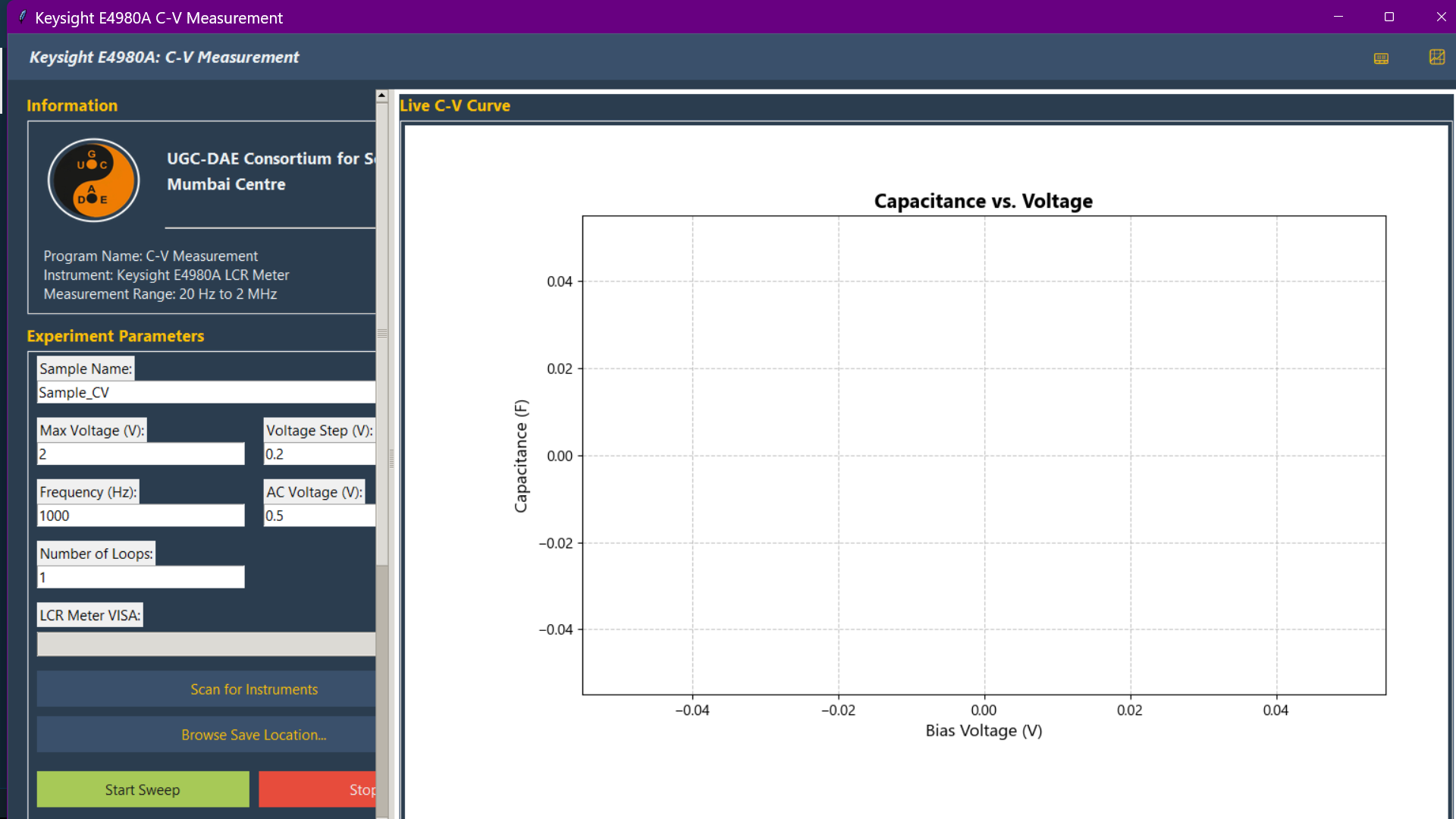
Capacitance-Voltage (C-V) characterization of a device or a sample using a Keysight E4980A LCR meter.
6.8 Broadband Dielectric Spectroscopy
Target Hardware: Novocontrol Alpha-AN Impedance Analyzer with a ZG4 sample interface, over direct GPIB. Frequency Range: 3 µHz to 20 MHz (this module sweeps a fixed 20 Hz – 1 MHz logarithmic series, 115 points).
Scientific Objective: Measures the complex permittivity (ε’, ε’’), electric modulus (M’, M’’) and AC conductivity (σ’, σ’’) of a dielectric sample at fixed temperature. Output is written in a WinDETA-compatible format so it opens directly in Novocontrol’s WinFIT analysis tool, alongside a PICA
.datfor the built-in Plotter.Reference Calibration: Use the dedicated Run REF Calibration button before a measurement session. It must run with the sample disconnected from the ZG4 (the GUI prompts you). Calibration data is stored inside the mainframe and survives resets, so a sweep runs on the most recent calibration; the GUI logs the calibration’s age but never blocks on it.
Note
This mainframe has no DC bias hardware — the module never transmits a bias command. A stale reference calibration shows up as a step or kink in ε’(f) at a reference-capacitor switch boundary rather than as uniform noise; re-run the REF calibration if you see one.
6.9 Standalone Temperature Utilities
Target Hardware: Lake Shore 350 Temperature Controller.
PICA also includes standalone utilities for monitoring and controlling temperature, independent of other measurement modules.
Temperature Monitor: A simple interface for logging temperature from multiple types of sensors.
Temperature Control: A dedicated module for setting temperature ramps, controlling heater outputs, and managing control loops.
Step-wise Control (Basic): A step-sequence controller that ramps to each setpoint, waits for stabilization, and hands off to an external measurement.
Step-wise Control (Advanced) (new in v1.0.5): A self-contained advanced version of the step-sequence controller. It adds an adaptive ramp rate (computed per step and hard-capped by an editable low-temperature rate table, taming overshoot on LN2-dewar probes below 100 K), an optional approach-from-one-side mode for hysteresis-sensitive measurements, configurable stability criteria (tolerance band, rolling window, drift limit, timeout), and per-setpoint summary logging alongside safety features such as a hard kill-switch temperature and a soft Max-Temp limit with graceful abort.
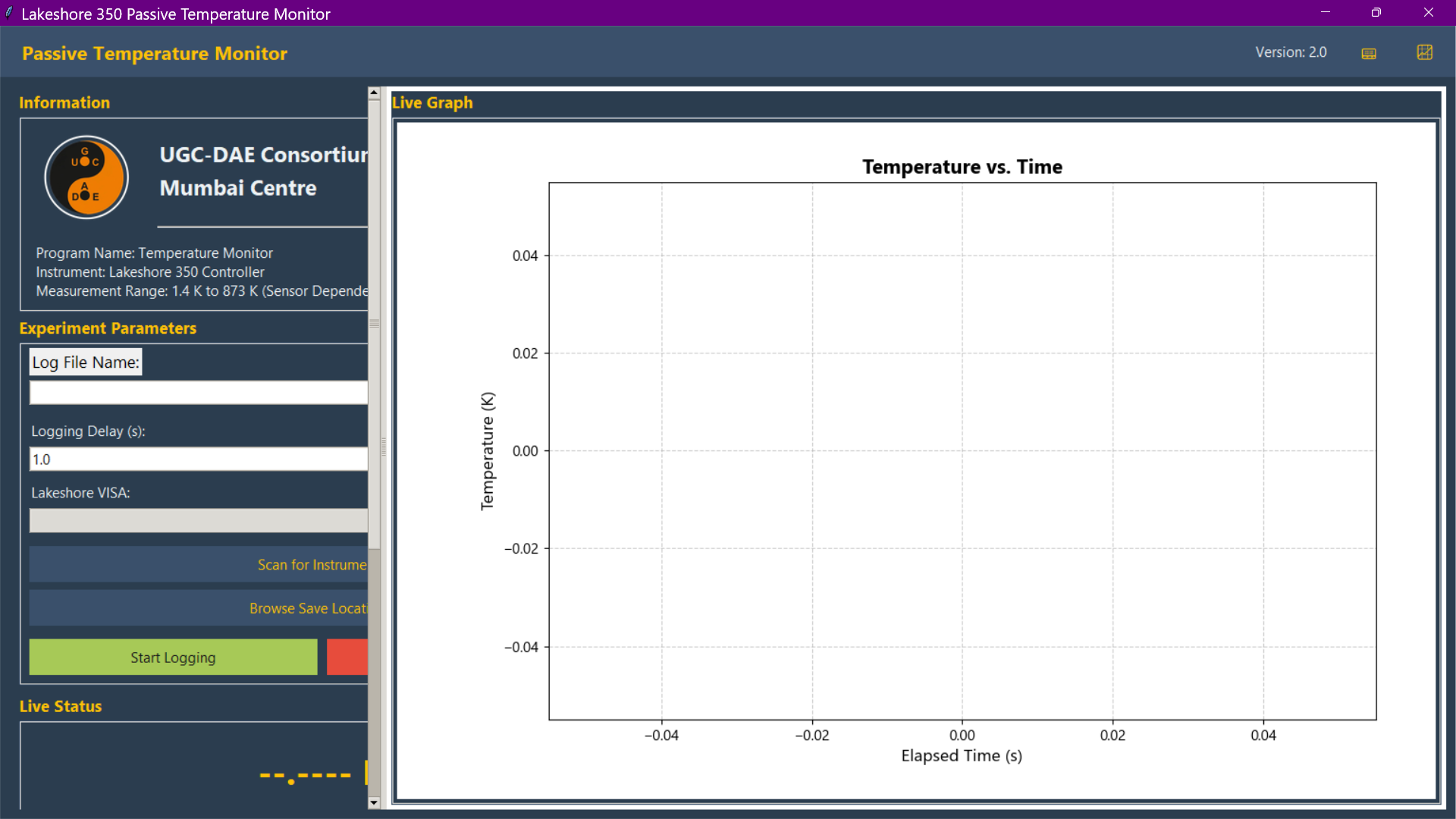
The standalone Temperature Monitor utility, used for logging data from a Lakeshore 350 controller.
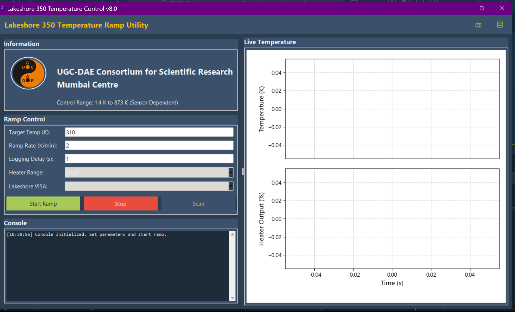
The standalone Temperature Control utility, providing a dedicated interface for managing temperature ramps and heater outputs on a Lakeshore 350.
6.10 Bench Multimeter Logging (Keithley 197A)
Target Hardware: Keithley 197A Autoranging Microvolt DMM.
A single-instrument logger for the Keithley 197A. It sets the measurement
function and range, then polls the meter and records the reading against time
with a live plot, until stopped. All seven functions are exposed (DC volts,
AC volts, 2-wire ohms, 4-wire ohms, DC amps, AC amps and dB), with autorange
as the default. The module ships in the usual two forms, a Tkinter GUI
(Monitor_K197A_GUI.py) and a headless twin
(Monitor_K197A_Instrument_Control.py).
Two things set this module apart from every other one in PICA, and both matter before you use it:
The interface card is required. The 197A has no built-in IEEE-488 bus. Remote control is only possible with an add-on Model 1973A (or 1972A) interface fitted to the meter. Those cards speak IEEE-488-1978, which predates both IEEE 488.2 and SCPI, so there is no
*IDN?identify query and no colon-prefixed command anywhere in this module. If nothing answers at the configured address, the module reports a plain diagnosis naming the missing card rather than raising an error, and points you at the GPIB Scanner utility.The command table is UNVERIFIED. The single-letter device-dependent commands (
Ffor function,Rfor range,Xto execute) are collected in one dictionary at the top of each file, marked as unverified. They have not been confirmed against hardware or against a machine-readable manual; the authoritative source is the printed Model 1973/1972 IEEE-488 Interface Instruction Manual. Correct that one dictionary from the manual before trusting any reading. Use the SCPI Console utility if you need to try command strings against the meter by hand. Every data file written by the module carries the line# Command table verified against manual: NOin its header as a reminder.
The reply format is likewise undocumented to us, so readings are parsed defensively: the first floating point number in the reply is taken as the value, and both the parsed value and the full raw string are written to the data file. A reply with no number in it is logged and written with a blank value rather than stopping the run. Units come from the selected function, not from the reply.
The poll interval is a GUI field defaulting to 1.0 s, with a hard floor of 0.34 s because the meter’s own maximum is 3 readings per second. Anything faster is clamped, and the clamp is announced in the console.
The default VISA address is the placeholder GPIB0::7::INSTR. It is editable
in the GUI, and it is very likely wrong on your rack; run the GPIB Scanner
utility to find the real one.
6.11 AC Transport (Keithley 6221 AC Current Source)
Target Hardware: Keithley 6221 AC/DC current source, paired either with an SRS SR830 DSP lock-in amplifier or with a Keithley 197A bench DMM. Optional thermometry from a Lakeshore 350 or a Cryo-con 34.
Ten modules in two matched sets of five. Each set covers the same four-probe AC measurement in the same four situations, so a measurement can be moved between the two detectors without changing anything else:
Protocol |
6221 + SR830 |
6221 + 197A |
|---|---|---|
AC I-V (current sweep, fixed f) |
|
|
AC frequency scan (fixed I) |
|
|
R–T, this module drives the ramp |
|
|
R–T, passive (Lakeshore 350) |
|
|
R–T, passive (Cryo-con 34) |
|
|
The SR830 set lives in pica/lockin/sr830/, beside the existing
AC_Resistivity_K6221_SR830_GUI.py; the 197A set lives in
pica/keithley/k6221_k197a/.
The current is set, not measured. The 6221 is a true current source, so
in both sets the current through the sample comes from the setting.
SOUR:WAVE:AMPL is a peak amplitude while every voltage here is RMS, so
the conversion happens once, explicitly:
I_rms = I_peak / sqrt(2)
Dividing an RMS voltage by a peak current gives a resistance wrong by exactly
sqrt(2) = 1.414 — large enough to matter, small enough to look plausible.
That factor is pinned by the test suite in every one of the ten modules.
With the SR830 (phase sensitive). R = X / I_rms, the in-phase
and therefore resistive part; the magnitude sqrt(X^2 + Y^2) / I_rms
is logged beside it, and the two agreeing to a fraction of a percent is the
evidence that the phasing is right and the contact is ohmic. The lock-in needs
a reference and the 6221 supplies it as a 1 µs TTL phase-marker pulse:
6221 TRIGGER LINK line 3 → SR830 REF IN. This cable is not optional. Without it the SR830 free-runs and every number it returns is meaningless.
Each point reads LIAS? and compares the SR830’s FREQ? against the
frequency programmed into the 6221, so a missing reference cable is reported
as an error and written into the file’s Flags column rather than logged as a
plausible resistance. Overloads and a reading above 90 % of the sensitivity
full scale are flagged the same way.
With the 197A (magnitude only). R = V_rms / I_rms.
The 197A on AC volts is a broadband true-RMS converter with no reference
input: there is no X, no Y and no phase. Nothing outside the drive
frequency is rejected, so mains hum, thermal EMF at the wrong phase, amplifier
noise and the harmonics of a non-ohmic contact all add in quadrature and
always upward — V_measured = sqrt(V_signal^2 + V_noise^2) >= V_signal —
which makes the reported resistance an upper bound. Use this pairing
when the voltage is comfortably above the meter’s noise floor and no lock-in
is free; use the SR830 pairing for anything small. Three consequences are
visible in the module:
the spread across the averaged readings is logged next to the mean, because with no reference it is the only noise estimate there is;
a drive outside the meter’s AC volts band is flagged on every point, since outside it the meter simply rolls the signal off and the resistance is low by an unknown factor;
everything in §6.10 about the 197A still applies — the Model 1973A/1972A interface card is required, and the command table is UNVERIFIED against the printed interface manual.
Temperature. The T-Control modules stabilise at the start temperature, arm
SETP and RAMP on the Lakeshore 350, open the heater and log along the
ramp, with a safety cutoff beyond the end temperature. The heater is put back
to off when the run ends, is stopped, or throws — in the same thread that
opened it, on every exit path, exactly as the current is. The T-Sensing
modules never write to their thermometer at all: whatever is driving the
temperature keeps driving it. The Cryo-con variants verify that the chosen
channel is displaying Kelvin before the run starts, parse the Cryo-con status
strings (-------, .......) rather than handing them to float(), and
retry the first *IDN? of a session.
Every module writes the standard PICA commented-header .dat file (§9.4),
with optional bar or van der Pauw resistivity and sheet resistance columns,
and takes the 6221 output off on every exit path.
Status: experimental. The pairings work and the conversions are tested, but neither set has been through a full measurement campaign.
7. Releases and Versions
For downloadable release builds, please visit the Releases page.
8. Common Issues & Troubleshooting
This section covers the most common issues encountered when using PICA.
8.1 VISA Timeout Error or Resource Not Found
This is the most frequent issue and usually indicates a problem with the connection between the computer and the instrument. Follow these steps to resolve it:
Check Physical Connections: Ensure all cables (GPIB, USB, Ethernet) are securely connected to both the instrument and the computer.
Use the VISA Scanner: Run the VISA Instrument Scanner utility from the PICA launcher.
If the instrument appears in the list, the connection is working. Note the correct VISA address.
If the instrument does not appear, PICA cannot see it. Proceed to the next steps.
Power Cycle the Instrument: Turn the instrument off, wait a few seconds, and turn it back on. This can often resolve temporary communication hangs.
Restart the Computer: If the problem persists, a full restart can resolve driver or backend issues.
Shut down the computer completely, leaving the instrument turned off.
Start the computer.
Once the system is fully booted, run the PICA VISA scanner.
Turn on the instrument.
Check Drivers and Communication Mode:
Ensure you have the correct VISA backend installed (see the
A VISA Backend is Requiredwarning in the Installation & Setup section).If using a different communication interface (e.g., switching from GPIB to USB), verify that the necessary drivers are installed and that the instrument is configured for that mode.
8.2 Instrument Control and Delays
An important parameter to consider during concurrent control of instruments is the delay. The time between each step should be sufficient to ensure that all instruments (whether two or three) have completed their commanded actions. Sending a new command before an instrument has had time to process the previous one will definitely cause errors. It is also important to introduce proper delays for the system to reach equilibrium. Furthermore, during the initial setup, instruments should be given adequate delay time for all their internal components to stabilize and enter a ready state. In PICA, sufficient internal delays are provided in all modules. However, it was observed that some systems might need more delay time. Therefore, a parameter for initial delay is available in those modules’ GUI. Users should provide an appropriate initial delay time. This initial delay time parameter is in addition to the basic delay already contained in the module.
8.3 Forcing a Re-installation for Debugging
You can force a clean re-installation of the package from the source directory.
This command removes the old installation and replaces it with a fresh build.
pip install . --force-reinstall
9. Technical Reference
9.1 File Naming Convention
To ensure data integrity and easy sorting, PICA automatically generates filenames using a standardized format. This allows for easier parsing by external analysis tools.
Format: [SampleName]_[Timestamp]_[Identifier].dat
Example: SampleA_2025-12-04_1430_IV_Sweep.dat
9.2 GPIB Address Guide
PICA uses standard VISA resource strings. While the defaults below are common, users should verify their specific instrument addresses using the built-in Instrument Scanner or front-panel settings.
Lake Shore 350:
GPIB1::15::INSTRKeithley 2400:
GPIB1::4::INSTRKeithley 6221:
GPIB0::13::INSTRKeithley 2182:
GPIB0::7::INSTRKeithley 6517B:
GPIB1::27::INSTRKeysight E4980A:
GPIB0::17::INSTRNovocontrol Alpha-AN:
GPIB0::5::INSTR
9.3 Repository Mirroring
This project is manually backed up weekly to a GitLab repository.
9.4 Data File Format
The data file includes a commented header line (starting with #) that contains metadata, such as the sample name. This is followed by a header row with column names and then the data rows.
This structure makes it easy to import the data into various analysis programs like Origin, or to parse it programmatically with libraries like Pandas.
Example: Ultra Low Resistance (I-V) Module
# Sample: Delta_Test_10ohm
Set Current (A),Measured Voltage (V),Resistance (Ohm)
-1.000000e-05,-1.037917e-04,1.037917e+01
-9.797980e-06,-1.017006e-04,1.037975e+01
Most other data files generated by PICA follow a similar structure.
10. Citation & Open Source
Collaborative Ecosystem: PICA is open-source (MIT License) to foster transparency. By providing the source code, the measurement protocols become auditable, ensuring that experimental conditions are reproducible and not hidden behind a proprietary “black box.” We encourage other research groups to adapt these scripts for their specific hardware configurations.
For the full preprint, please refer to the Preprint section.
10.1 Preprint
The full preprint of the PICA software suite, detailing its design, implementation, and applications, is available for review.
Preprint Page: https://prathameshnium.github.io/PICA-Python-Instrument-Control-and-Automation/publications/
Direct PDF Download: https://prathameshnium.github.io/PICA-Python-Instrument-Control-and-Automation/publications/pica-paper.pdf (alternate link at Academia.edu)
Citation:
@software{Deshmukh_PICA_2026,
  author       = {Deshmukh, Prathamesh Keshao and Mukherjee, Sudip},
  title        = {{PICA: Advanced High-Precision Transport Measurement Automation with Python}},
  month        = jan,
  day          = 26,
  year         = 2026,
  publisher    = {Zenodo},
  version      = {1.0.5},
  url          = {https://doi.org/10.5281/zenodo.18377217}
}
11. Future Development
11.1 AC Resistivity (Lock-In)
Status: Under Development. The first modules have landed and are described in §6.11 — I-V, frequency scan and R-T, with either the SR830 or a Keithley 197A as the voltmeter. What remains is a full measurement campaign against a known sample, and the verification of the 197A command table against its printed interface manual.
Instruments: Keithley 6221 (AC Source) + SRS SR830 (DSP Lock-In Amplifier).
Predicted Resistance Range: ~ 20 nΩ to 1 MΩ.
Scientific Objective: Probes frequency-dependent transport phenomena.
Use Case: Useful for distinguishing between different conduction mechanisms by analyzing the frequency response of the sample’s resistance.
Workflow: The Keithley 6221 provides a precise AC excitation current, while the Lock-In Amplifier (SR830) extracts the signal amplitude and phase with high noise rejection, allowing for accurate ac resistivity measurements.
11.2 Standalone Executables
In the future, we also plan to develop executable (.exe) versions of the PICA software suite. This will remove the need for users to manage Python environments and dependencies, further simplifying the setup process and facilitating rapid adoption in laboratories.
11.3 New Utilities and Analysis Modules
We plan to add more utility modules, such as a PID simulator for temperature controller PID values calibration and various simple data analysis modules. These additions will help to streamline the entire process from measurement to analysis, making PICA a more self-contained ecosystem.
12. Adding a New Instrument
The procedure for adding a new instrument module to PICA is described in the CONTRIBUTING.md file. Please refer to that guide for detailed, step-by-step instructions.
13. Authors & Acknowledgments

Lead Developer: Prathamesh Deshmukh
Principal Investigator: Dr. Sudip Mukherjee
Affiliation: UGC DAE Consortium for Scientific Research, Mumbai Centre, Bhabha Atomic Research Centre, Mumbai, 400 085, Maharashtra, India
Funding
Financial support for this work was provided under SERB-CRG project grant No. CRG/2022/005676 from the Anusandhan National Research Foundation (ANRF).
14. License
This project is licensed under the MIT License - see the LICENSE file for details.
15. Appendix A: Project File Structure
For developers and advanced users, the following reference outlines the PICA directory structure (abridged, v1.0.5).
Note
Adding a new module to the main launcher into the GUI requires modifying pica/main.py.
For launcher v2, add the same module to CATALOG in pica/main_v2.py so it
appears in Advanced Options, and to QUICK_CATALOG in the same file if it also
belongs on the Quick Select screen.
PICA (Root Directory)/
    .coveragerc
    .gitignore
    CHANGELOG.md
    CITATION.cff
    CODE_OF_CONDUCT.md
    CONTRIBUTING.md
    LICENSE
    MANIFEST.in
    README.md
    pica_cli.py
    pyproject.toml
    requirements-dev.txt
    requirements.txt
    run_pica.py
    .github/
        workflows/
            codeql.yml
            draft-pdf.yml
            lint.yml
            test.yml
    docs/
        Instruments_Manuals_Lists.md
        User_Manual.md
    examples/
        examples.md
    paper/
        paper.bib
        paper.md
    pica/
        __init__.py
        cli.py
        main.py
        assets/                 <-- Images, Logos, Icons
            Images/
            LOGO/
        keithley/
            delta_mode/         <-- Low Resistance (K6221 + K2182)
                Delta_RT_K6221_K2182_L350_Sensing_GUI.py
                Delta_RT_K6221_K2182_L350_T_Control_GUI.py
                IV_K6221_DC_Sweep_GUI.py
                Instrument_Control/
            k2400/              <-- Mid Resistance (K2400 Standard)
                IV_K2400_GUI.py
                RT_K2400_L350_T_Control_GUI.py
                RT_K2400_L350_T_Sensing_GUI.py
                Instrument_Control/
            k2400_2182/         <-- Mid Resistance (High Precision)
                IV_K2400_K2182_GUI.py
                RT_K2400_K2182_L350_T_Sensing_GUI.py
                RT_K2400_K2182_T_Control_GUI.py
                Instrument_Control/
            k6221_k197a/        <-- AC transport with a DMM (magnitude only)
                IV_AC_K6221_K197A_GUI.py
                Frequency_Scan_K6221_K197A_GUI.py
                RT_AC_K6221_K197A_L350_T_Control_GUI.py
                RT_AC_K6221_K197A_L350_T_Sensing_GUI.py
                RT_AC_K6221_K197A_CC34_T_Sensing_GUI.py
            k6517b/             <-- High Resistance & Pyroelectric
                High_Resistance/
                    IV_K6517B_GUI.py
                    RT_K6517B_L350_T_Control_GUI.py
                    RT_K6517B_L350_T_Sensing_GUI.py
                    Instrument_Control/
                Pyroelectricity/
                    Pyroelectric_K6517B_L350_GUI.py
                    Instrument_Control/
        keysight/               <-- Capacitance (E4980A)
            CV_KE4980A_GUI.py
            Instrument_Control/
        novocontrol/            <-- Broadband Dielectric (Alpha-AN)
            Frequency_Scan_AlphaAN_GUI.py
            Instrument_Control/
        lakeshore/              <-- Temperature Control
            T_Control_L350_RangeControl_GUI.py
            T_Sensing_L350_GUI.py
            Instrument_Control/
        lockin/                 <-- Lock-in Amplifiers (Experimental)
            sr830/
                Comms_SR830_GUI.py
                AC_Resistivity_K6221_SR830_GUI.py
                IV_AC_K6221_SR830_GUI.py
                Frequency_Scan_K6221_SR830_GUI.py
                RT_AC_K6221_SR830_L350_T_Control_GUI.py
                RT_AC_K6221_SR830_L350_T_Sensing_GUI.py
                RT_AC_K6221_SR830_CC34_T_Sensing_GUI.py
                Instrument_Control/
        utils/                  <-- Core Utilities
            GPIB_Instrument_Scanner_GUI.py
            GUI_Basic_Format.py
            PlotterUtil_GUI.py
            parser.py
    tests/                      <-- Automated Test Suite
        conftest.py
        test_backends_logic.py
        test_deep_simulation.py
        test_entry_points.py
        test_full_stack_simulation.py
        test_gui_layouts.py
        test_gui_modules_initialization.py
        test_package_integrity.py
        test_pica_launcher.py
        test_utilities_logic.py